Phant0mas’ Place

Coding, building, debugging

My August Hacking Update

| Comments

August out!

August is almost over. The same could be said for the summer, but I am in Greece. I will probably still be using A/C at least until November :P. The first half of the month was really productive, but then I removed two of my wisdom teeth and I had to take it easy. Anyhow let’s see what I got done.

My work on Guix

Guix master
1
2
3
4
5
6
7
8
$ git log --since="last month" --author=Manolis  --pretty='format:%h %cd %s' --date=format:'%Y-%m-%d' --reverse
9ef5940ce 2017-08-02 gnu: calibre: Add python2-msgpack as an input.
5638d7150 2017-08-03 gnu: openscenegraph: Add 'Release' configure flag.
c608fe8cf 2017-08-09 gnu: Add ois.
2d5bf32b8 2017-08-09 gnu: googletest: Build shared libraries.
dd75a9a22 2017-08-17 gnu: Add ogre.
42d0d13de 2017-08-17 gnu: Add mygui.
e9a599cdc 2017-08-17 gnu: Add OpenMW.

While I thought packaging OpenMW would take me longer, I managed to track the dependencies, package them, and make the tests work with some serious two week work.
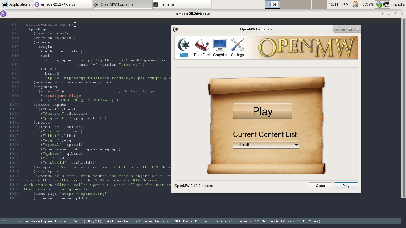
Let’s say now that you are thinking about contributing to OpenMW, and you are also using Guix (or GuixSD). Here is how you can setup your environment, fast:

OpenMW Environment
1
2
3
4
manolis@prometheus ~/repos/openmw $ guix environment openmw  --pure
substitute: updating list of substitutes from 'https://mirror.hydra.gnu.org'... 100.0%
manolis@prometheus ~/repos/openmw [env]$

And just like that you have an environment with all the openmw dependencies and you are ready to start hacking.

Smart Home Project

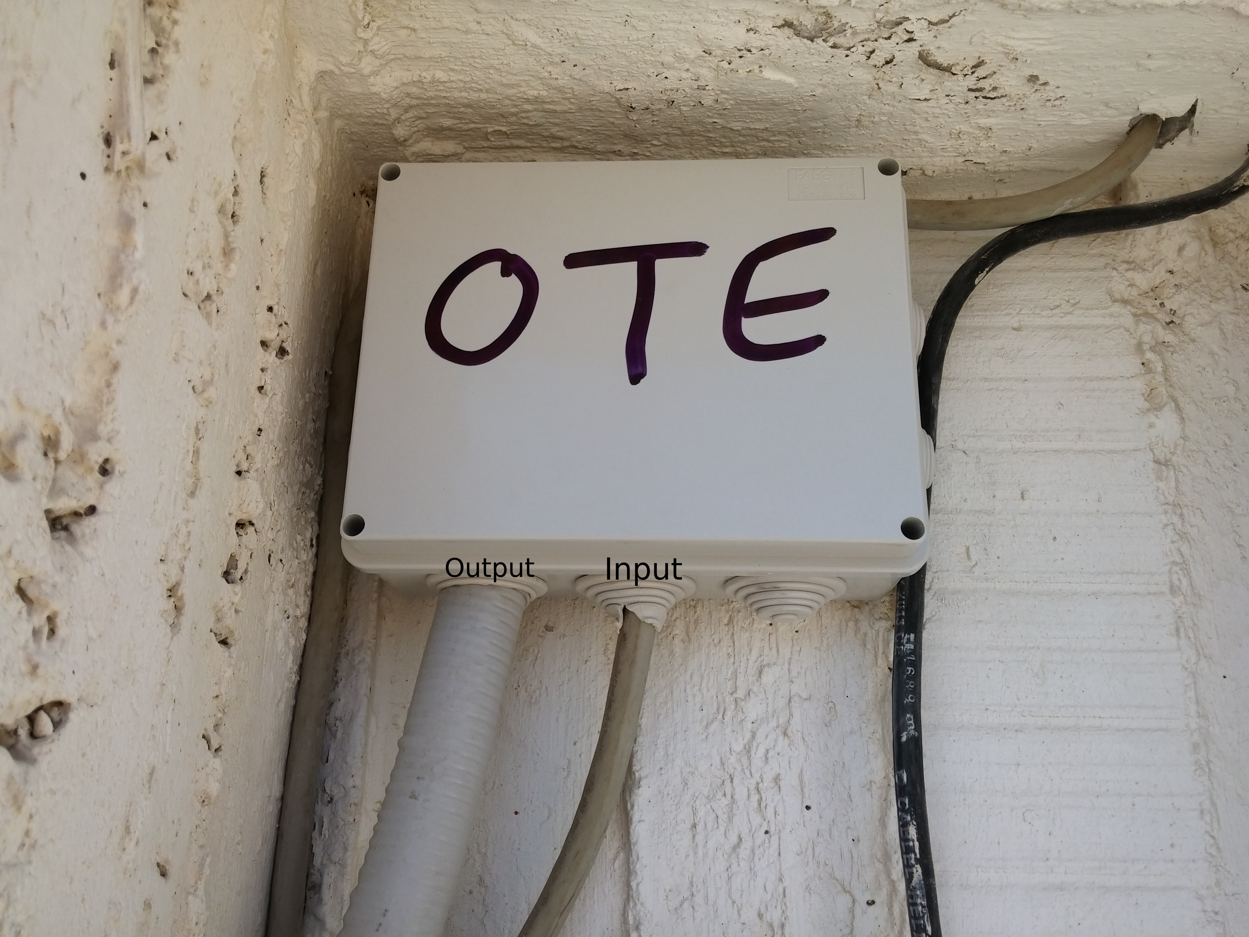
The home project is moving forward. The windows will probably arrive next week (they are currently being painted.) and today I connected the new cat6 underground lines to the phone company’s (OTE) cables. It was a miracle how the old cables were still working, as they were in a miserable condition. I think the result speaks for itself.

I also started working on the hardware for the smart locks. I experimented a bit on my room’s door and this is the prototype.
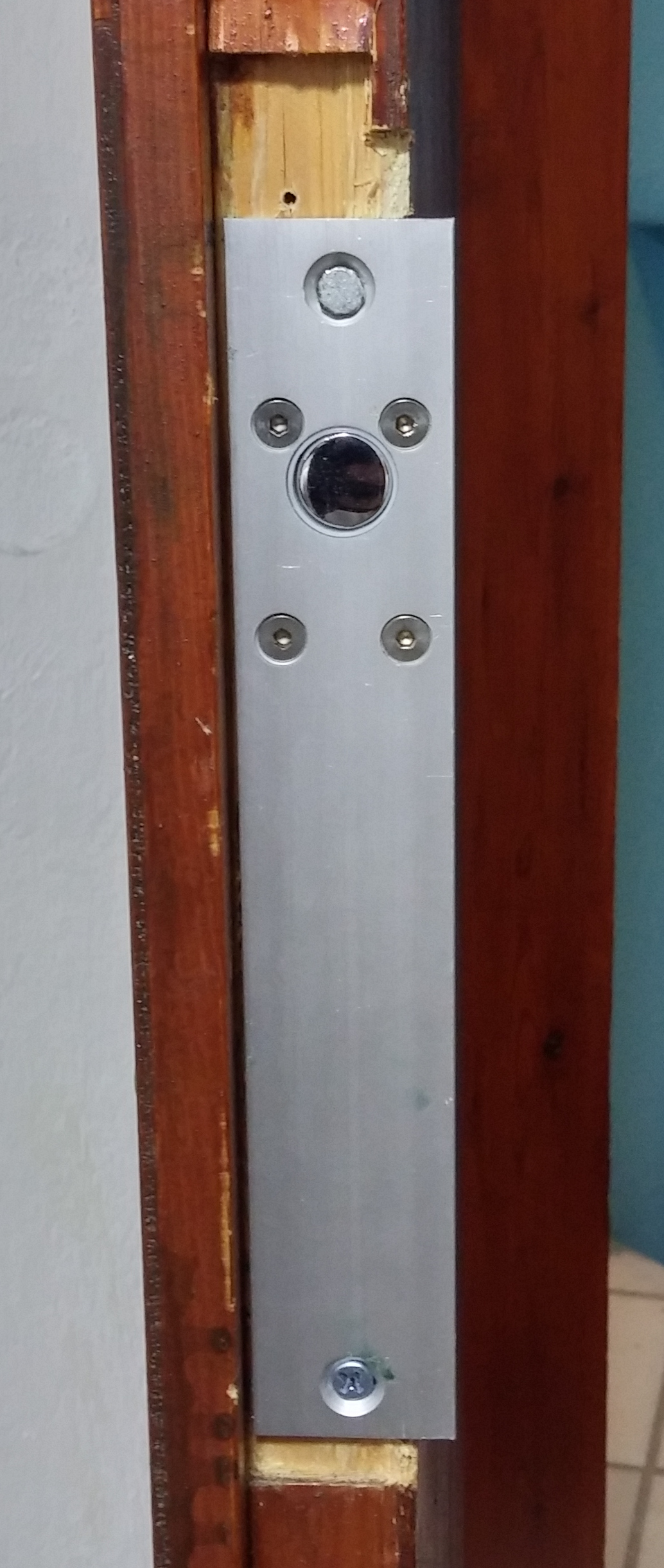
I am using an Arduino and a mosfet to drive the 12V electric lock. I am also planing to install a cover with a keypad on the outside of the door. Mainly as a way to open the door in case I forget my phone and to cover the missing parts of the door :P.

Reading Books

There are some books that every CS student should read in order to call himself one. One of those is “Structure and Interpretation of Computer Programs” or SICP for short. This book has enough material to teach you more than most students learn in Greek universities in 4 years time. And I finally got my hands on a hard copy!!

September is coming

In the first 10 days of September I expect to install the new windows/doors in the house so I can finally get the new home network online. I will then be able to start activating the smart home mechanisms and show everyone what I have in mind. I also definitely hope that September will finally be the month I get to finish my thesis text and defend it. We will see how it will go.

Manolis out.

My Hacking Adventures.

| Comments

Long time no see

It’s been a long time since I last updated this blog. Between my studies, the last two GSoCs I was a part of and my personal life I had little time to spend on this blog. Now this will change. With this post I will tell you a little about some of the things I am working on and some goals I have in mind.

I hope that by the end of this post my mind will be better organized and get more productive!

My work on Guix and Hurd

Two years ago I announced that I successfully ported GNU Guix to GNU Hurd. But that didn’t mean that everything was done. During GSoC 2016 I started working on creating a Hurd based GuixSD system. Unfortunately the time frame was not enough and it needed more work. But I have continued working on it and hopefully I will be able to deliver a working image soon. I also have help from a fellow hacker called Rene, and which I am really thankful.

I try to push all of my work to the upstream Guix repo, but sometimes my code doesn’t meet the standards. As a result the day to day hacking happens in a github repo.

I will write another post on how to use that repo to actually try Guix on Hurd yourself.

Things that work:

  • Guix can cross-build or build natively most of the packages needed for a GNU system and others.

Things I need to finish:

  • There is a library I wrote for the Hurd called libhurdutil which I need to clean and finally push to Hurd.
  • Use the library above to finish implementing build isolation in the Guix daemon while on Hurd.
  • Fix the packages that cannot be build but are needed for a GNU system.

My work on Guix (but not Hurd :P)

I am using Guix in my everyday life a lot! This mean I had to add a couple of packages, not related to Hurd, in the span of these last 4 years .

Currently I need to finish:

  • The GNU Radio package.
  • The Open MW package. (I have already packaged its dependencies)

My thesis on L4/Fiasco

The purpose of this thesis is to offer isolation between processes, where a process can be a simple app that read from a sensor to a fully fledged Linux system. And all this on top of a zynq board, called zedboard, which is an FPGA + arm CPU. The plan is to control which process access what hardware. While running on the same system. And did I mention Fiasco is a microkernel? It sounded cool to me!

While the thesis did have some setbacks, which I will talk in another post, it has advanced enough to think that I will be able to defend it sometime in September.

Currently I need to:

  • Solve issues with accessing time controllers from inside the processes.
  • Write the thesis text.

In a future post I will get into the inner working of my thesis. Until then if you are not aware of L4/Fiasco please visit here.

My smart home project

A year go I was given the opportunity to finish the unfinished building which is directly upstairs from the one I am now. Suddenly the idea came. Why not automate as much as I can!? Create a house which will learn its occupants. Design everything from scratch. And I started.

For the sake of not making the post longer than it is now, I will redirect you to my twitter feed and my conversations with David Thompson. In the near future I will add a post which I will get into the details of the house.

This blog

David has created a static site generator called haunt in scheme. Eventually I want to move this blog to haunt.

Grand Plan?

Is this my Grand Plan? Well I am mostly seeing this as a way to bring my thoughts in order and create a plan for the next six months. It doesn’t necessarily mean that I will manage to finish everything but it’s a good way to understand what I want to do, by actually trying to explain everything in my head and in my notes to other people.

By the end of this 6 months period, I will do my best to complete these goals!

Manolis out.

Debug a Running Linux Kernel on the Zedboard With GDB

| Comments

Disclaimers

I am sharing what works for me. It may not work for you or it may fail over time. You may suffer data loss or worse. I disclaim all warranties and representations.

Prerequisities

  • Xilinx Microprocessor Debugger (XMD)
  • GDB capable of understanding the target machine

Debugging the Kernel

When developing a device driver, having access to the linux internals using GDB may be the key to meeting that deadline. On the zedboard, debugging the kernel with GDB is actually very easy with the help of the Xilinx Microprocessor Debugger, or XMD for short.

XMD is included with the Vivado Design Suite from Xilinx. In case you are working with the older ISE Design Suite, the included XMD should work as well.

Start debugging

  • Connect the JTAG to the zedboard (or a micro usb to the PROG USB port) and boot it.
  • Open a shell and run xmd.
shell
1
2
3
4
5
6
7
user@workstation ~ $: xmd
Xilinx Microprocessor Debugger (XMD) Engine
Xilinx EDK 14.7 Build EDK_P.20131013
Copyright (c) 1995-2012 Xilinx, Inc.  All rights reserved.

XMD%
XMD%
  • Run connect arm hw. This will start a GDB server at localhost:1234.
shell
1
2
3
4
5
6
7
8
9
10
11
12
13
14
15
16
17
18
19
20
21
22
23
24
25
XMD% connect arm hw

JTAG chain configuration
--------------------------------------------------
Device   ID Code        IR Length    Part Name
 1       4ba00477           4        Cortex-A9
 2       23727093           6        XC7Z020

--------------------------------------------------
Enabling extended memory access checks for Zynq.
Writes to reserved memory are not permitted and reads return 0.
To disable this feature, run "debugconfig -memory_access_check disable".

--------------------------------------------------

CortexA9 Processor Configuration
-------------------------------------
Version.............................0x00000003
User ID.............................0x00000000
No of PC Breakpoints................6
No of Addr/Data Watchpoints.........4

Connected to "arm" target. id = 64
Starting GDB server for "arm" target (id = 64) at TCP port no 1234
XMD%
  • Open a new shell and go to the directory where the kernel sources are located, the ones you used to build the kernel, and run arm-xilinx-eabi-gdb vmlinux.

    In my case I am using arm-xilinx-eabi-gdb but any gdb cross-build for arm will do. We are passing vmlinux to the debugger, so it can read the kernel symbols.

shell
1
2
3
4
5
6
7
8
9
10
user@workstation ~/git_repos/linux-analog $: arm-xilinx-eabi-gdb vmlinux
GNU gdb (Sourcery CodeBench Lite 2013.11-46) 7.6.50.20130726-cvs
Copyright (C) 2013 Free Software Foundation, Inc.
License GPLv3+: GNU GPL version 3 or later <http://gnu.org/licenses/gpl.html>
This is free software: you are free to change and redistribute it.
There is NO WARRANTY, to the extent permitted by law.  Type "show copying"
and "show warranty" for details.
...
Reading symbols from /home/manolis/git_repos/linux-analog/vmlinux...done.
(gdb)
  • Then, under the GDB command prompt, enter: target remote localhost:1234
shell
1
2
3
4
5
(gdb) target remote localhost:1234
Remote debugging using localhost:1234
cpu_v7_do_idle () at arch/arm/mm/proc-v7.S:74
74        ret lr
(gdb)
  • And now GDB is ready for debugging those kernel hangs. Enter continue in the gdb prompt so linux can continue it’s normal operation. You can come back anytime and stop it in order to debug it.

Extras

  • Make sure you have enabled the kernel debug symbols in the config file of the kernel. Enabling CONFIG_DEBUG_INFO will do the trick.

Setup a Linaro GNU/Linux Enviroment on the ZedBoard

| Comments

[Notice: This guide is outdated, but works. I will upload a guide for newer sources sometime in the future!]

Before we start

Disclaimers: I am sharing what works for me. It may not work for you or it may fail over time. You may suffer data loss or worse. I disclaim all warranties and representations. This guide is based on the one from digilent which you can find here, and the one from Jan Gray which you can find here.

For this guide I used an Arch GNU/Linux x86_64 box and the Xilinx ISE Design Suite, version 14.7 which you can get from here. This guide will probably work on any GNU/Linux box which can run the Xilinx tools, but I can’t guarantee anything. If you are using another os, it will probably work with some modifications, but I can’t guarantee that either.

In this post I will guide you through the process of getting a headless Linaro GNU/Linux system running on the ZedBoard. For those of you not familiar with the ZedBoard, which I highly doubt since you are here, read this.

So, why run Linaro on Zedboard?

Well, there are two main reasons for that:

  1. Linaro comes with a working gnu toolchain so you can actually build and debug directly on it, without the need of your main workstation.
  2. As it is based on Ubuntu, you can have access to the large collections of programs in its repos, making the customization of the system a lot easier.

What we’re going to build

  • An XPS design for ZedBoard, which we’ll export to the SDK.
  • A u-boot.elf (Linux boot loader).
  • An FSBL (first stage boot loader) using the SDK.
  • The linux kernel.
  • A devicetree blob named devicetree.dtb.
  • A FAT32 partition on our SD card that comprises these files BOOT.BIN, uImage, and devicetree.dtb.
  • An ext4 partition on our SD card with the pre-built Linaro Ubuntu userland .

Prerequisities

  • Just make sure ISE 14.7 w/ EDK is there and working.

Prepare the SD card

To boot the system on the ZedBoard you’ll need a SD memory card. The SD card should have at least 4 GB of storage and it is recommended to use a card with speed-grade 6 or higher to achieve optimal file transfer performance. The SD card needs to be partitioned with two partitions. I suggest to make the first one be about 256MB in size and the second one should take up the remaining space. For optimal performance make sure that the partitions are 4MB aligned. The first partition needs to be formatted with a FAT filesystem. It will hold the bootloader, devicetree and kernel images. Name it ZED_BOOT. The second partition needs to be formatted with a ext4 filesystem. Name it ROOT_FS. It will store the systems root filesystem. Use whatever tool you want to do it :-).

Building the programmable logic hardware

  • Download the reference design for ZedBoard from here.
  • Create a folder named tutorial.
  • 1
    
    $ mkdir tutorial
  • Change folder to tutorial.
  • 1
    
    $ cd tutorial
  • Unzip the file you download above, in here.
  • 1
    
    $ unzip ../ZedBoard_Linux_Design.zip .
  • Change folder to ZedBoard_Linux_Design.
  • 1
    
    $ cd ZedBoard_Linux_Design
  • Open system.xmp file in hw/xps_proj with xps.
  • 1
    
    $ xps hw/xps_proj/system.xmp &
  • Click yes when asked to upgrade cores to newer version.
  • Click Generate BitStream and start making fun of windows l-users play some ksp work-ahead on the u-boot and linux kernel steps below, while you check back on the progress on this step. When it’s finished, check if there are no errors and pretend you don’t see the warnings.
  • Click Export Design. Select Export and Launch SDK. (Continued below.)

Build u-boot, the Linux boot-loader

  • If you have properly installed the ISE suite in your box, you should already have the ARM cross compile toolchain installed, which will work just fine.
  • Fetch the source:
  • 1
    
    $ git clone https://github.com/Digilent/u-boot-digilent.git ../u-boot-digilent ; cd ../u-boot-digilent
  • Build u-boot with the cross-compile tools
  • 1
    2
    
    $ make  CROSS_COMPILE=arm-xilinx-linux-gnueabi- zynq_zed_config
    Configuring for zynq_zed board...
    1
    
    $ make  CROSS_COMPILE=arm-xilinx-linux-gnueabi-
  • After the compilation, the ELF (Executable and Linkable File) generated is named u-boot. We need to add the ‘.elf’ extension to the file name so that Xilinx SDK can read the file layout and generate BOOT.BIN. In this tutorial, we are going to move the u-boot.elf to boot_image folder and substitute the u-boot.elf that comes along with ZedBoard Embedded Linux Design Package.
  • 1
    
    $cp u-boot ../ZedBoard_Linux_Design/boot_image/u-boot.elf 

Generate the boot image BOOT.BIN

  • This consists of the FSBL (first stage boot loader), the system.bit configuration bitstream, and the U-boot Linux boot-loader u-boot.elf. Follow exactly the instructions.
  • By now xps should have finished generating the bitstream. So at xps, export the hardware design to Xilinx SDK by clicking on Project -> Export Hardware Design to SDK
  • Click Export & Launch SDK
  • Set Workspace to ZedBoard_Linux_Design/hw/xps_proj/SDK/SDK_Export and click ok
  • After SDK launches, the hardware platform project is already present in Project Explorer on the left of the SDK main window. We now need to create a First Stage Bootloader (FSBL). Click File->New->Project
  • In the New Project window, select Xilinx->Application Project, and then Click Next.
  • We will name the project FSBL. Select xps_proj_hw_platform for Target Hardware because it is the hardware project we just exported. Select standalone for OS Platform. Click Next.
  • Select Zynq FSBL as template, and click Finish
  • For the ZedBoard, we need to reset the USB PHY chip by toggling the USB-Reset pin in the FSBL. Add the following code to main.c of the FSBL project after the line 565
  • 1
    2
    3
    4
    5
    6
    7
    8
    9
    10
    11
    12
    13
    14
    15
    16
    17
    18
    19
    20
    21
    22
    23
    
        /* Reset the USB */
    
        fsbl_printf(DEBUG_GENERAL, "Reset USB...\r\n");
    
        /* Set data dir */
        *(unsigned int *)0xe000a284 = 0x00000001;
    
        /* Set OEN */
        *(unsigned int *)0xe000a288 = 0x00000001;
        Xil_DCacheFlush();
    
        /* For REVB Set data value low for reset, then back high */
    #ifdef ZED_REV_A
        *(unsigned int *)0xe000a048 = 0x00000001;
        Xil_DCacheFlush();
        *(unsigned int *)0xe000a048 = 0x00000000;
        Xil_DCacheFlush();
    #else
        *(unsigned int *)0xe000a048 = 0x00000000;
        Xil_DCacheFlush();
        *(unsigned int *)0xe000a048 = 0x00000001;
        Xil_DCacheFlush();
    #endif
  • After you have saved the changes to main.c, the project will rebuild itself automatically. If it does not rebuild, Click Project->Clean to clean the project files, and Project->Build All to rebuild all the projects. The compiled ELF file is located in ZedBoard_Linux_Design/hw/xps_proj/SDK/SDK_Export/FSBL/Debug/FSBL.elf
  • Now, we have all the files ready to create BOOT.BIN. Click Xilinx Tools -> Create Zynq Boot Image.
  • In the Create Zynq Boot Image window, choose Create new Biff file and click Browse. Go to tutorial-zedboard/ZedBoard_Linux_Design/boot_image/ path and type BOOT.bif as the filename you want. It does not yet exist but it will get created.
  • Next in the Boot image partitions area click add, choose Partition type -> bootloader, add the FSBL.elf found at ZedBoard_Linux_Design/hw/xps_proj/SDK/SDK_Export/FSBL/Debug/ to the file path and click ok.
  • Click add again, Partition type -> datafile, add to the file path the system.bit found at ZedBoard_Linux_Design/hw/xps_proj/SDK/SDK_Export/xps_proj_hw_platform/ and click ok.
  • Repeat the above, but this time add u-boot.elf found at ZedBoard_Linux_Design/boot_image/.
  • Finally click Create Image and a file named output.bin is generated in the ZedBoard_Linux_Design/boot_image folder.
  • Change the name of output.bin to BOOT.BIN and you are done.
  • 1
    2
    
    $ cd ZedBoard_Linux_Design/boot_image
    $ mv output.bin BOOT.BIN

Build the Linux Kernel

  • Get the Linux kernel source code from Digilent git repository. Make sure you are in the tutorial root folder.
  • 1
    2
    3
    
    $ pwd
    /home/something/tutorial
    $ git clone https://github.com/Digilent/linux-digilent.git linux-digilent ; cd linux-digilent
  • We will start to configure the kernel with the default configuration for ZedBoard. The configuration is located at arch/arm/configs/digilent_zed_defconfig. To use the default configuration, you can use:
  • 1
    
    $ make ARCH=arm CROSS_COMPILE=arm-xilinx-linux-gnueabi- digilent_zed_defconfig
  • We will keep the default kernel configuration, so use the command bellow and then just press exit.
  • 1
    
    $ make ARCH=arm CROSS_COMPILE=arm-xilinx-linux-gnueabi- menuconfig
  • Build the Kernel
  • 1
    
    $ make ARCH=arm CROSS_COMPILE=arm-xilinx-linux-gnueabi-
  • After the compilation, the kernel image is located at arch/arm/boot/zImage. Copy it to the boot_image folder.
  • 1
    
    $ cp arch/arm/boot/zImage ../ZedBoard_Linux_Design/boot_image/

Build the device tree

  • Note your DTS file arch/arm/boot/dts/digilent-zed.dts if it includes these bootargs:
  • 1
    2
    
    bootargs = "console=ttyPS0,115200 root=/dev/mmcblk0p2 rw earlyprintk rootfstype=ext4 rootwait devtmpfs.mount=1";
    /* bootargs = "console=ttyPS0,115200 root=/dev/ram rw initrd=0x800000,8M init=/init earlyprintk rootwait devtmpfs.mount=1"; */
  • That’s good — Linux will mount your root file system from the second partition on your SD card.
  • Generate DTB file.
  • 1
    2
    
    $ ./scripts/dtc/dtc -I dts -O dtb -o ../ZedBoard_Linux_Design/boot_image/devicetree.dtb arch/arm/boot/dts/digilent-zed.dts 
    DTC: dts->dtb  on file "arch/arm/boot/dts/digilent-zed.dts"

Start copying to sd card

  • Copy to the ZED_BOOT partition of the sd card, that has the FAT filesystem, the files BOOT.BIN, devicetree.dtb, zImage that we created before, found in the ZedBoard_Linux_Design/boot_image folder.
  • Now it’s time to download the Linaro image, which you can find here.
  • Create a folder under /tmp named linaro, and copy the zipped Linaro image to it.
  • 1
    2
    3
    
    $ mkdir -p /tmp/linaro
    $ sudo cp linaro-saucy-developer-20140410-652.tar.gz /tmp/linaro/fs.tar.gz
    $ cd /tmp/linaro/
  • Unpack the disk image using the tar command.
  • 1
    2
    3
    
    $ sudo tar -xvf fs.tar.gz
    $ ls
    binary     fs.tar.gz
    
  • Unmount any automatically mounted partitions of the sd card.
  • Mount the SD Card to /tmp/sd_ext4. Make sure to replace the device node with the device node of the ext4 partition on your SD Card.
  • 1
    2
    
    $ mkdir -p /tmp/sd_ext4
    $ sudo mount /dev/sdX2 /tmp/sd_ext4
  • Use the command rsync to copy the root file system onto the SD card. This command will preserve those attributes that should remain unchanged.
  • 1
    2
    3
    4
    
    $ cd binary/
    $ pwd
    /tmp/linaro/binary
    $ sudo rsync –a ./ /tmp/sd_ext4
  • Unmount before removing the SD card to make sure all the files have been synchronized to it. Unmounting /tmp/sd_ext4 may take several minutes, but you must wait to see that umount returns before removing the SD card.
  • 1
    
    $ umount /tmp/sd_ext4
  • Everything is ready!!

Booting the SD Card

Once you complete these guide instructions, the SD card will have everything it needs to boot Linux on the ZedBoard. Complete the procedures in steps 1-7 to test your SD card with the ZedBoard.

  1. Insert the SD card into the ZedBoard.
  2. Set the jumpers on the ZedBoard as follows:
    • MIO 6: set to GND
    • MIO 5: set to 3V3
    • MIO 4: set to 3V3
    • MIO 3: set to GND
    • MIO 2: set to GND
    • VADJ Select: Set to 1V8
    • JP6: Shorted
    • JP2: Shorted
    • All other jumpers should be left unshorted
  3. Attach a computer running a terminal emulator to the UART port with a Micro-USB cable. Configure the terminal emulator with the following settings:
    • Baud: 115200
    • 8 data bits
    • 1 stop bit
    • no parity
  4. Attach a 12V power supply to the ZedBoard and power it on.
  5. Connect to the appropriate port in the terminal emulator. You should begin to see feedback from the boot process within a few seconds, depending on the speed of the SD card.
  6. Wait for the boot process to complete. If it gets stuck at the u-boot prompt just type reset and it will work.
  7. You now have a complete GNU/Linux system running on the ZedBoard.